3 June, 2020
AN AEROBATIC GLIDER
Completed project
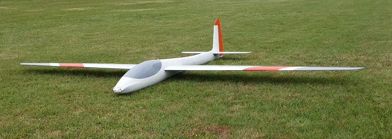
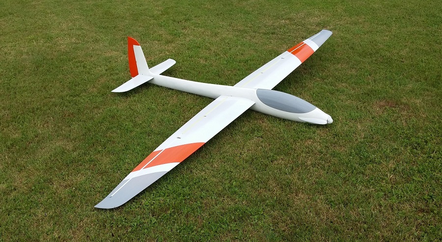
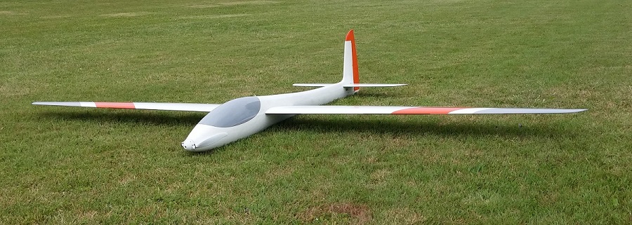
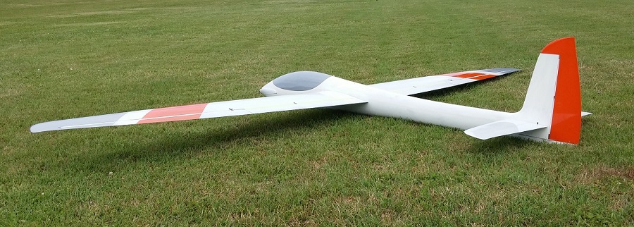
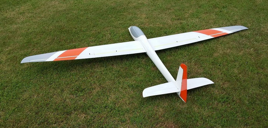
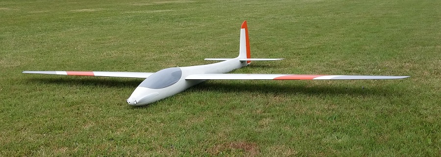
In the 3/2013 edition of Aufwind magazine I saw an article about the Wings & More Stingray. The model immediately struck a chord with me. I quickly started sketching using a couple of 3-views I found on the internet and soon had something that I was happy with. I did not bother trying to be too accurate, after all, there exists no fullsize version anyway. The changes that I made on purpose are
- change the shape of the canopy edge. I don’t like the traditional straight edges, so I went for a smooth curve
- position the elevator completely in front of the rudder
That was the easy part. But now how to build it, and to what size ? Luckily a friend also got interested and provided a lot of help, without him I would certainly not have gotten this to the finish line. We agreed on a wingspan of 2400mm. This initially seemed a bit small to me, but now that I have been flying it for a couple of years I must admit that it was a good choice. The size makes it very manageable for transport and launching. And in the air visibility is surprizingly good, probably because it is much more “bulky” compared to the F5J style models I was used to.
Below is a short description of the construction of the model. I am writing this a couple of years after the fact, so I did not want to spend much time going into all the details. I intend to put more effort in the story of the Confluence.
Fuselage
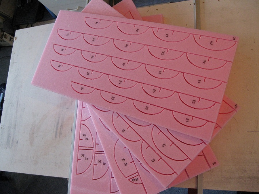
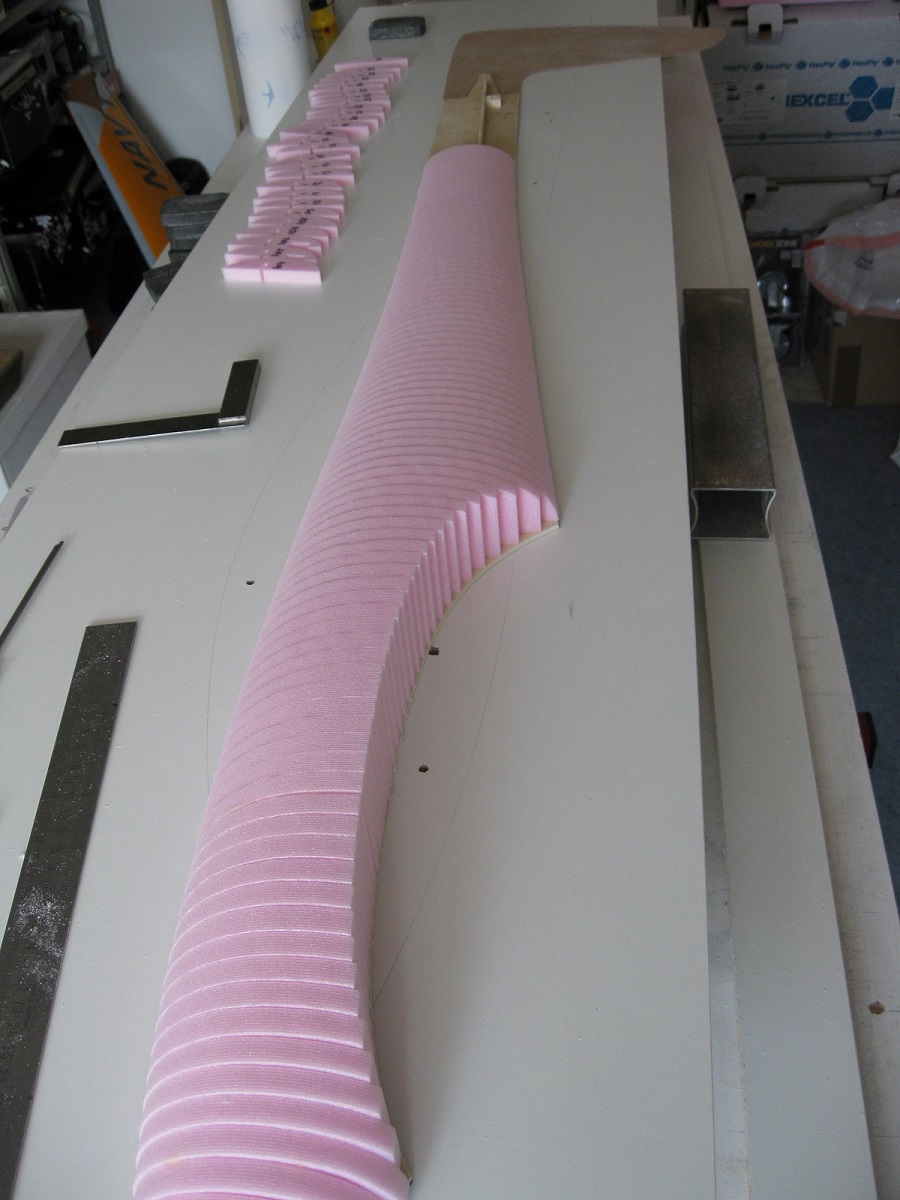
The plug for the fuselage was built by slicing the 3D-model in 10mm thick slices, cutting these out of foam on my CNC-mill and gluing them together. This was then grinded smooth and covered with a couple of layers of 160 gram glassfabric + epoxy. Finishing with lots of applications of filler, primer and 2K-paint. Finally polishing to obtain a mirror finish. Only a couple of words here but all of this took a long time. A special point of attention for me was obtaining a perfect fit of the canopy.
One special detail about the plug is that I made it in two halves and kept the halves separate during the whole process. Intention was to avoid the effort of making a separation plate exactly at the centerline. With separate halves I could just place the first plug half on a flat plate and laminate the first mold part. After removing the separation plate I glued the second plug half and laminated the second part of the mold. This worked out reasonably well (with some lessons learned for the next time), although I am still not sure if it was worth the effort.
(pictures below can be enlarged by clicking and swiping)
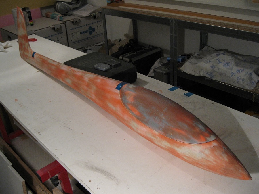
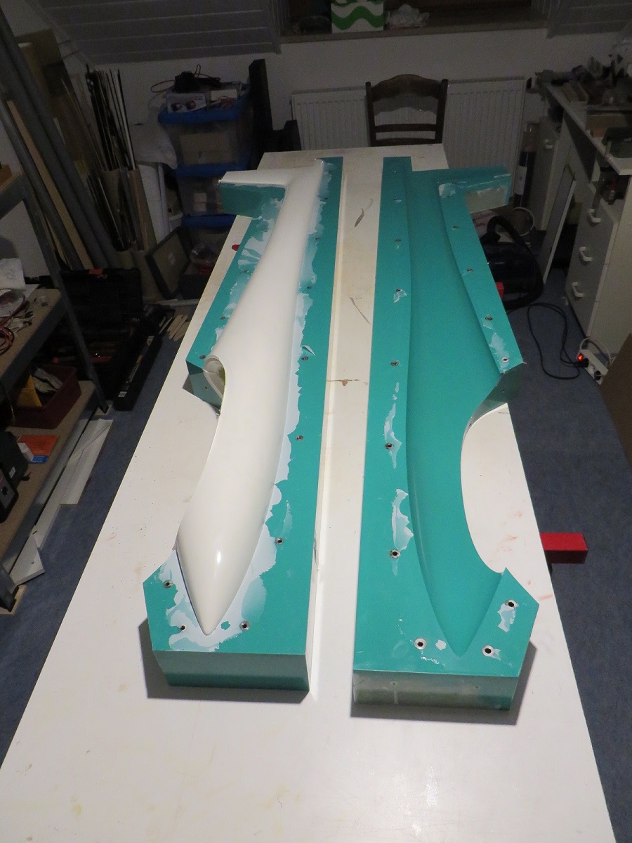
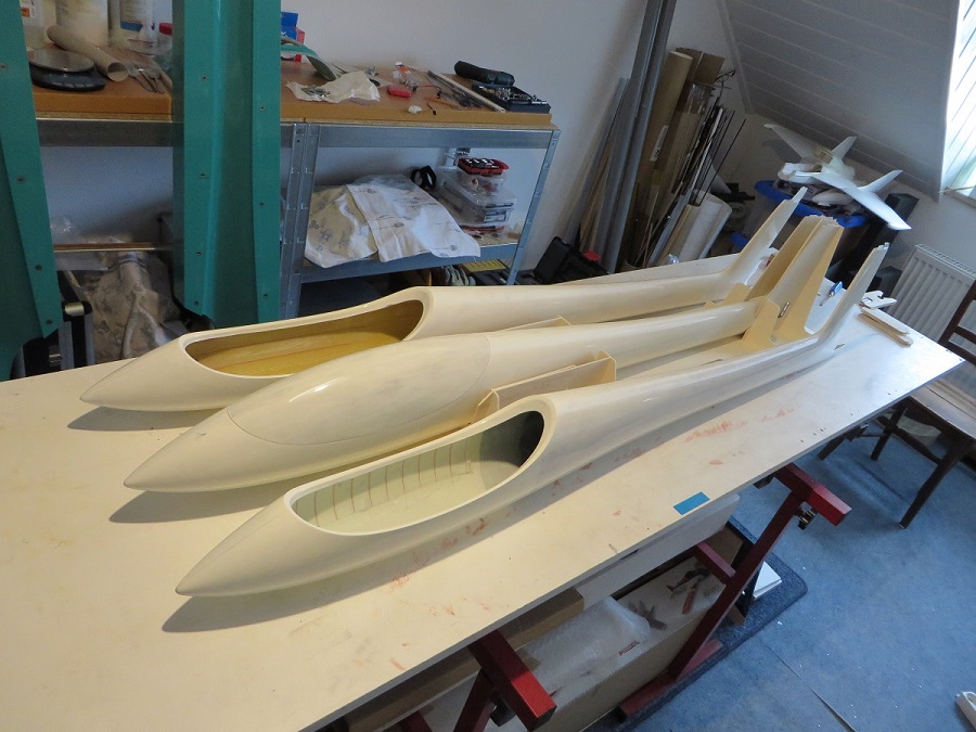
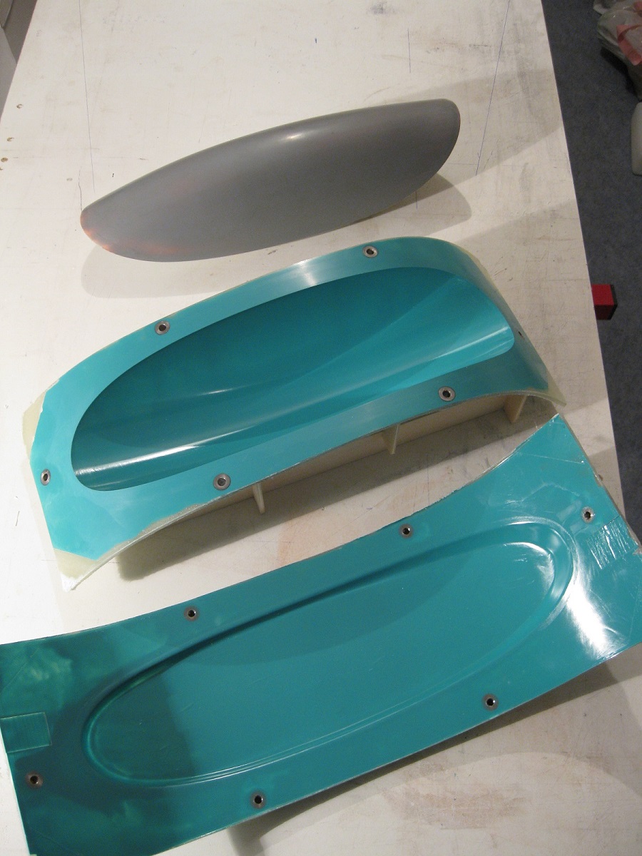
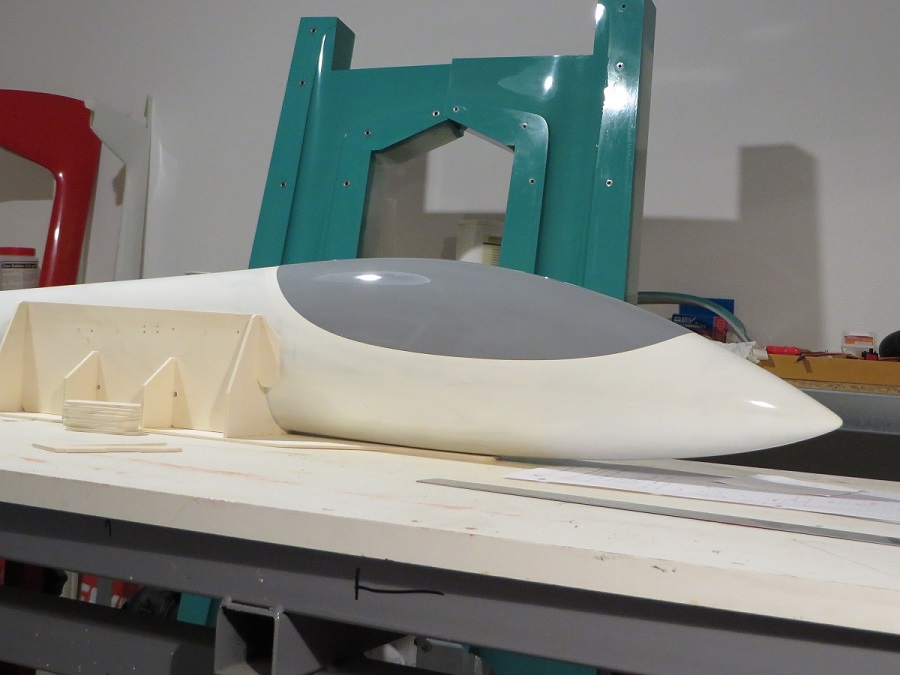
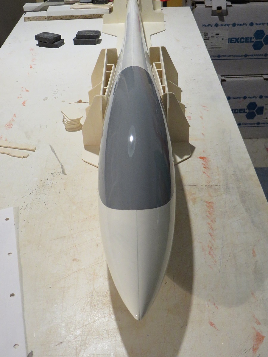
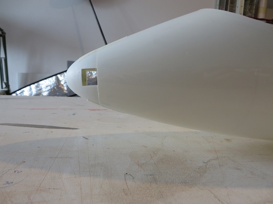
Three fuselages were laminated, first only glassfabric, then including some aramid fibre and the third one had an amount of carbon. That is the one I used for my model. My friend kept the aramid version.
The fuselage has no fairings for wing and stab, so an elaborate jig was manufactured out of liteply to mark the position of the alignment pins on the fuselage. The jig was also used to cut the nose at the correct position and position for a spinner. I am a flatland flyer and like to be independent to get my gliders in the air so an electric motor has to be part of the package.
Rudder
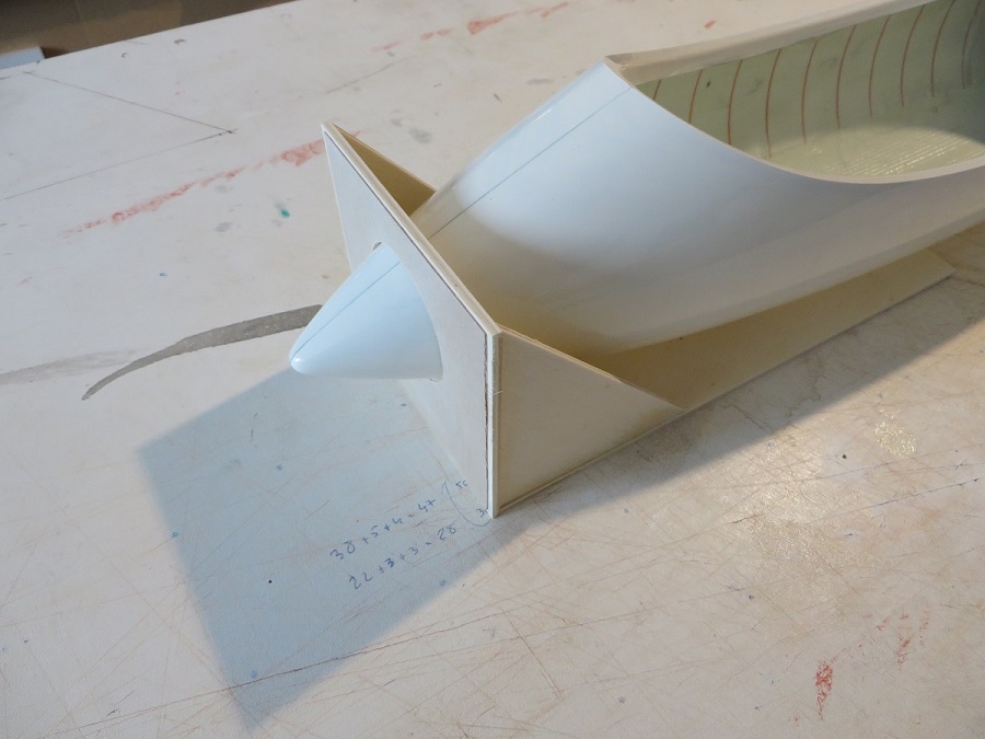
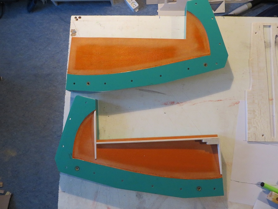
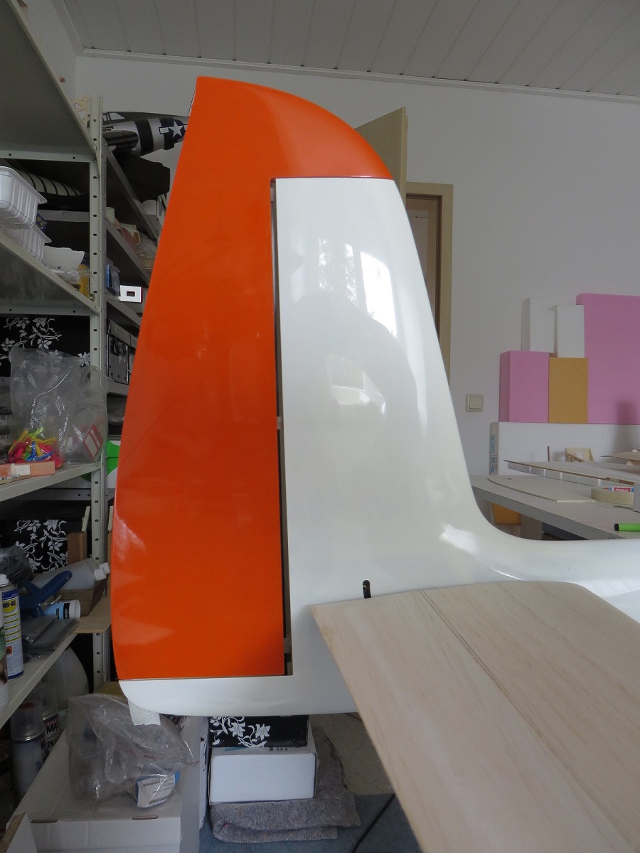
The rudder got its own mold. It was not possible to laminate the rudder together with the fuselage and use the skin for live-hinging because of the curvature of the skin at that location.
The second picture still shows a foam/balsa stab. This was replaced with a molded stab before the first flight.
Wing
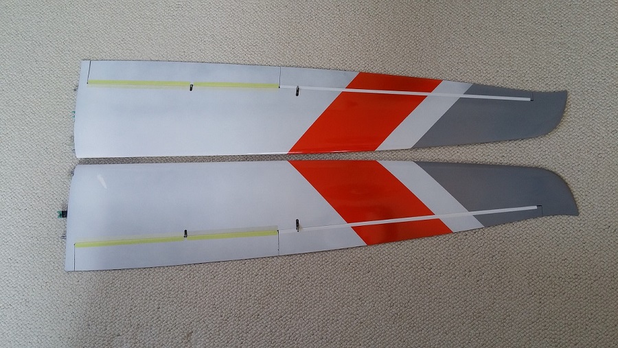
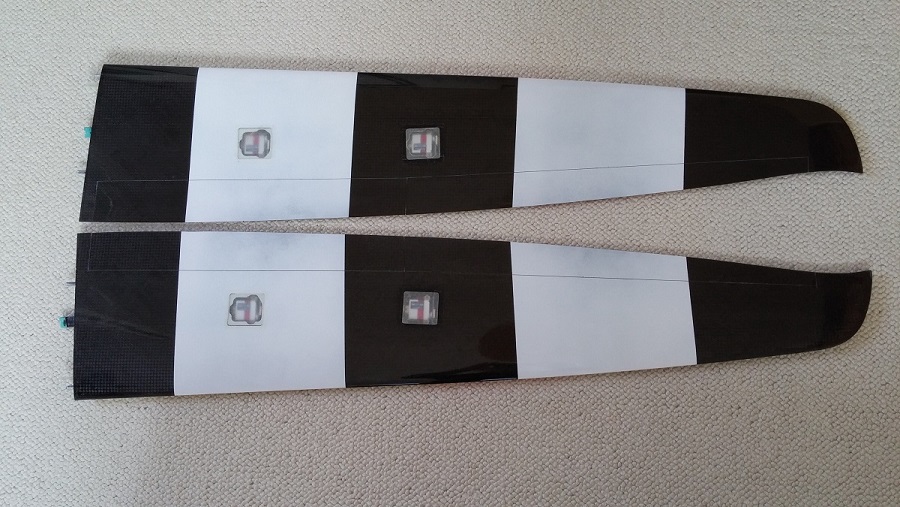
My friend did the work on the wing molds and while laminating the parts we unfortunately did not take any pictures. The sequence follows the established process of machining a plug out of tooling material, finishing this with 2K-paint, laying up the molds and finally laminating the wings. The wingskins are a sandwich of 65gram carbon fabric, a foam core and 72gram glass fabric. Of course it also includes sparcaps of UD-carbon fibre and a shearweb from endgrain balsa.
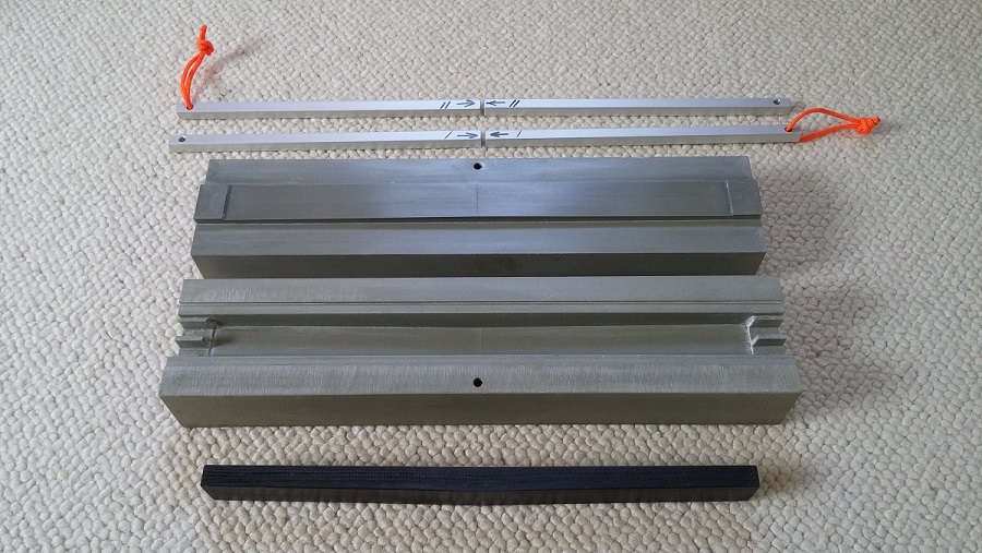
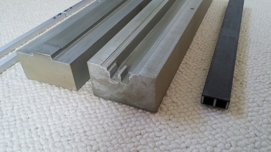
The mold for the wing joiner is machined out of high density tooling material. The joiner itself is tapered in thickness and is layed up with carbon UD and some carbon braid around the aluminium cores. Three plywood pieces fill up the remaining empty space.
Stabilizer
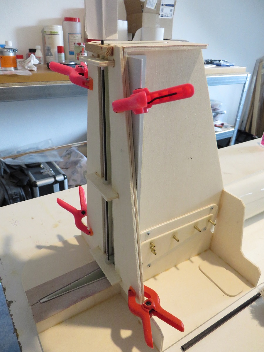
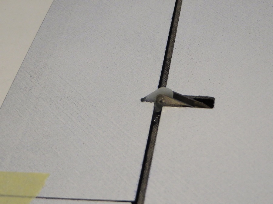
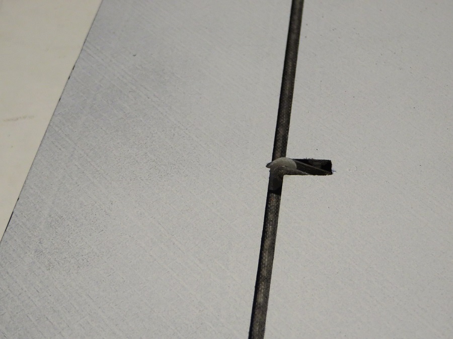
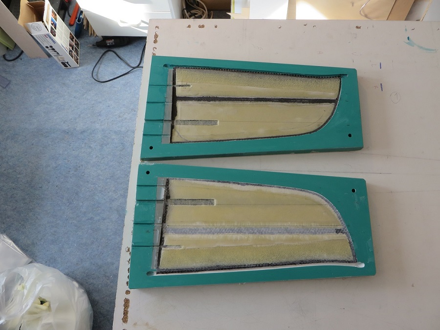
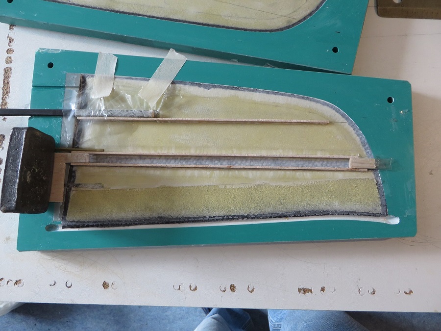
The stabilizer follows the same manufacturing process as the wing. My friend made the molds, but I made my own stabilizers so at least I can show a couple of pictures of that. Contrary to the more commonly used round joiner we used a 6x6mm square carbon tube.
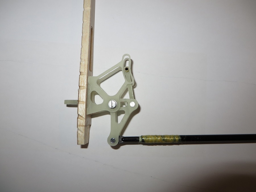
The parts of the elevator actuator are machined out of glass fibre plate material. Connection to the servo is with a carbon fibre tube.
Gear installation
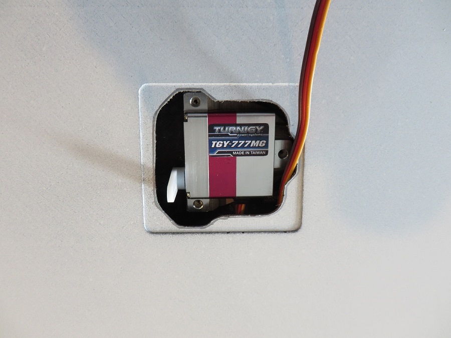
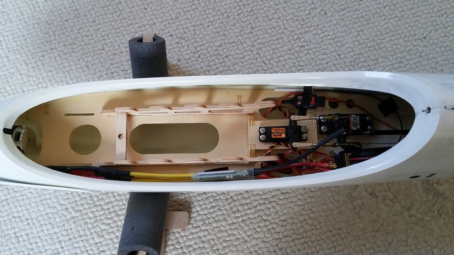
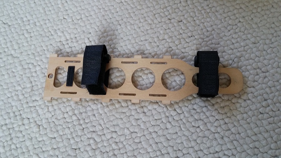
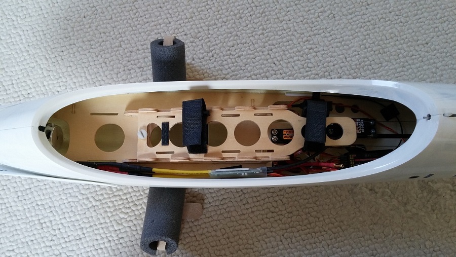
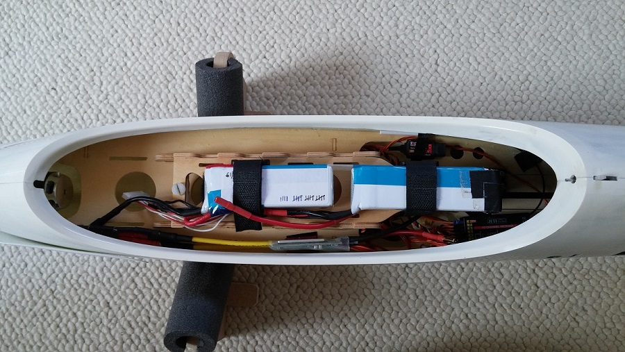
I was very happy with the power setup in my Jaro Muller Eldorado so I decided to do something similar here. It also allows me to use the battery packs for both models. The motor is a Peggy Pepper HK-2524-1950kV with a Reisenauer Micro-edition 5:1 gearbox. This is quite light which is an advantage with the long nose of the Stingray. Propeller is a 14x10. Controller is a YGE 65 LVT : small and light, a powerful BEC and telemetry capability to my Jeti transmitter. The battery consists of two 3S 1600mAh packs connected in series. This may not sound a lot but a (vertical) climb-out to approximately 200m normally uses no more than 100-150 mAh. For rudder and elevator servos I used what I had available. I had overestimated a bit the amount of weight I would need up front to balance the model, hence the need to move the battery backwards on top of the rudder servo. For the next model I will re-organize my installation setup.
“And across the finish line”
Flying weight ended up at 2830 gram, resulting in a wing loading of 62g/dm² (not counting the stabilizer surface). With this weight it responds to thermals well but is dynamic enough (for me) for nice aerobatics and fast fly-bys. No comparison to a real F3B model of course. Behavior at low speed is very docile, only dropping the nose and a slow wing drop to the left when overdoing it. Saying I am happy with the end result is an understatement.